You can check which drivers and samples are available for each board here: Downloads Do you need a driver which is not featured? Real-time applications with Windows and RTX drivers. Most ADDI-DATA PC boards are supplied with RTX drivers allowing you to create real-time applications for Windows. As RTX is multi-core, you can build your applications parallelly and split them on several processor cores.
Introduction
- You will find in our product range efficient high-tech products for the industrial measurement and automation. ADDI-DATA solutions can be found worldwide in numerous industrial areas: automotive and metal industry, engine building industry, tailor-made machinery, aircraft and chemicals industry, etc. They are used for quality control, process control, signal switching, data acquisition, motion control.
- The device driver of the ADDI-DATA GmbH APCI-7800 can implement a maximum transfer rate of up to 115.2 kilobits per second with or without the optical isolation. The maximum baud rate that can be supported by the device driver using a 20mA current loop would be limited to 19.2 kilobits per second.
- Welcome to ADDI-DATA for the USA! We offer high-quailty solutions for industrial measurement and automation in numerous areas. Our products are used for data acquisition, motion control, quality control, process control, signal switching, or position acquisition and automation.
- ADDI-DATA offers a wide range of distributed systems and PC based solutions for Linux (RTAI) and Windows users (RTX drivers). Increase the productivity of your facility by integrating our real-time systems in your processes! Product overview.
Laser Engraving Machine with ADDI-DATA I/O Card PA-310 is a PC-controlled system developed using our technology of Windows Device Drivers for Low-Level Motion Control Boards.
Main application area is supposed as laser inscription, engraving, marking, and cutting.
Main Features
- High-speed, single-table, high resolution 2-axis system
- Adjustable workpiece positions
- Flexible trajectory control
- Windows standard imaging software support (CorelDraw, AutoCAD, etc)
- HPGL, CNC controlling
- Wide range of resolutions
Component Parts
Hardware Components:

- IBM PC Compatible System with 2 ISA Slots
- ADDI-DATA IO Card PA-310
- CS&IE Interrupt Generating Board
- Siemens Silamatik Laser Marker
Software Components:
- Microsoft Windows 2000
- Windows 2000 Hardware Driver
- Windows 2000 Port Monitor Driver
- Windows 2000 Printer Driver
- Windows 2000 Motion Control Configurator
ADDI-DATA I/O Card PA-310
ADDI-DATA IO Card PA-310 is a product of ADDI-DATA GmbH.
The PC slot-in card contains all components necessary for numerical control of 2 coordinate axes. This card can meet the requirements of a variety of applications in the low power range.
Figure 1: ADDI-DATA I/O Card PA-310
Technical Data
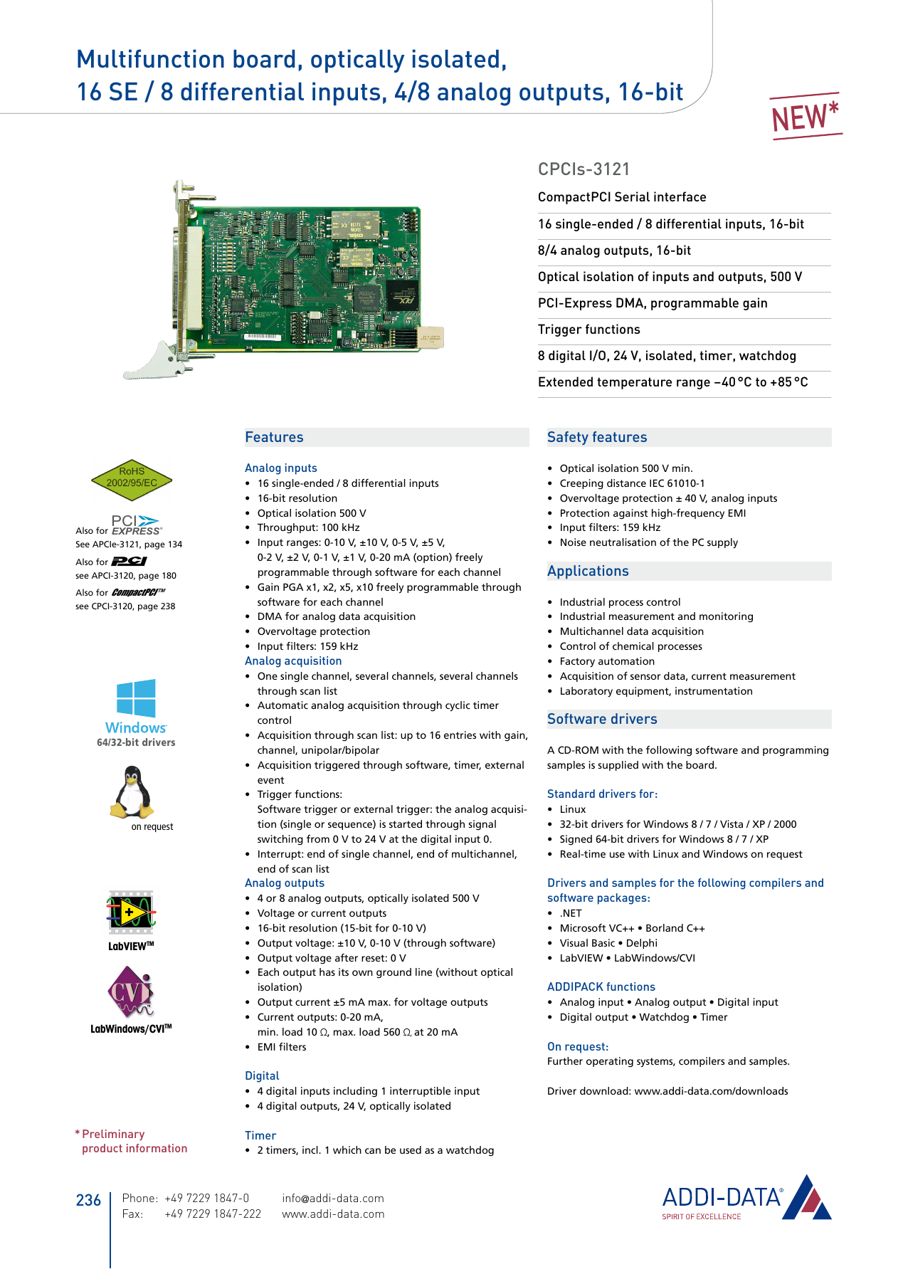
- 16 single-ended or 8 differential input channels
- 12-bit resolution
- conversion time: 25mks / channel (only A/D converter)
- output circuit protection
- outputs with output filers (option SF, DF)
- 0-2mA or 4-20mA voltage or current inputs (options SC, DC)
- converters outputs can be software sampled
- interrupts can be formed by using converters outputs
- software controlled analog outputs +-10V or 0…10V with 12-bit resolution
- small transition time
- 2 digital outputs
Siemens Silamatik Laser Marker
Siemens Silamatik Laser Marker consists of:
- Control YAG-Laser with Q-Switch
- Beam Deflection Head
- Flat Field Lens
- Marking Field 100 x 100 mm
Interrupt Generating Board
Drivers Addi-data 64
Our own Interrupt Generating Board was developed to support real-time control of the system under Windows 2000 operating system. It is based on three-channel one-chip programmable timer. Requirement of such a board is determined by the necessity of high-resolution timer with period of about 25 microseconds.
Figure 2: Interrupt Generating Board
Hardware Driver
Hardware Driver was developed to provide the possibility to work with various hardware systems that require control in real-time mode.
The Driver is fully configurable from application supplied with it. It is possible to enable or disable required axes, reverse axes, specify motion area, velocity and acceleration. There is a possibility for additional controlling parameters for various applications.
The Driver can accept input data in HPGL language, and it is capable to control external laser tools concurrently with the motion.
Together with Printer Driver, it is possible to use Windows standard graphical applications (such as CorelDraw, AutoCAD, etc) to control 2- coordinate systems and engrave vector or raster graphics generated by graphical applications.
Printer Driver
Printer Driver is intended to take part in rendering process together with GDI. It produces data in HPGL format with certain extension to implement features of specific machines that have differences in structure and functionality from usual plotters but are still closer to them than to any other computer peripherals.
Printer Driver is implemented like Windows Plotter Driver. It also has a set of pen options and a set of specific options for a machine.
Printer Driver works with vector and raster data. It distinguishes different colors reflecting them to tool parameters. For laser engraving machine, user can specify motion speed during drawing with configured pen as well as the power of laser tool corresponding to 'pen down' state for every pen. User is prompted to set the type and size of drawing area.
Port Monitor Driver
Port Monitor Driver consists of user-mode DLLs. It is responsible for providing a communication path between user-mode print spooler and kernel-mode port drivers that access I/O port hardware. It is also responsible for management and configuration of server printer ports.

Structure
Port Monitor consists of two DLLs:
Port Monitor User Interface DLL:
Port Monitor UI DLL contains user interface functionality and executes on print client systems. This DLL must reside in the client system System32 sub-directory.
Drivers Addi-data Drivers
Port Monitor Server DLL:
Port Monitor Server DLL contains port communication functionality and executes on print servers. It must not display a user interface.
Main Features
- Decoding of HPGL or CNC commands produced by standard or specialized software (e.g. CorelDraw, AutoCAD, etc) and translating them into basic commands of Hardware Driver.
- Distributed and local control of the laser engraving process.
- Setup and control over all parameters of Hardware Driver.
- Support of remote laser engraving process over LAN or Internet, allowing a single laser engraving machine being shared and controlled from several terminals.
User Interface
Screenshots of Port Monitor User Interface are shown in Figures 3-6.
Figure 3: Port Monitor Driver - Device Settings
Figure 4: Port Monitor Driver - Tool Settings
Figure 5: Port Monitor Driver - Preview Settings
Figure 6: Port Monitor Driver - Shortcuts Settings
Motion Control Configurator
Motion Control Configurator is a Windows tray application intended for easy one-click control of printing process. It provides a good alternative to standard Windows “Printer Settings” dialog.
Screenshots of Motion Control Configurator are shown in Figures 7-8.
Figure 7: Motion Control Configurator - Application Menu
Figure 8: Printer Driver Menu
Conclusion

Laser Engraving Machine with ADDI-DATA I/O Card PA-310 controls up to 2 coordinate axes of galvo mirrors with extremely high resolution and accuracy. Hardware and software set provides a very flexible and precise real-time control for a variety of applications in the low power range. Hardware Driver is configurable by the means of Motion Control Configurator. Together with Printer Driver, it is possible to use Windows standard graphical applications (such as Corel Draw, AutoCAD, etc) to control 2-coordinate systems. In combination with Printer and Port Monitor Drivers, the whole system is very flexible and convenient to use.
In order to activate the driver, the driver is included in the form dll0=addi_data.dll in the section [OEM].
Drivers Addi-data Xerox
The driver requires the section [addi_data], in which further parameters can be defined.
| Name of parameter | Default value | Description |
|---|---|---|
| Read8FC | 100 | Number of FC Read8DigitalInputs |
| Read16FC | 101 | Number of FC Read16DigitalInputs |
| Read32FC | 102 | Number of FC Read32DigitalInputs |
| Set8FC | 103 | Number of FC Set8DigitalOutputs |
| Set16FC | 104 | Number of FC Set16DigitalOutputs |
| Set32FC | 105 | Number of FC Set32DigitalOutputs |
| InitAnaInpFC | 106 | Number of FC InitAnalogInput |
| RelAnaInpFC | 107 | Number of FC ReleaseAnalogInput |
| InitAnaOutFC | 108 | Number of FC InitAnalogOutput |
| ReadAnaInpFC | 109 | Number of FC ReadAnalogInput |
| WriteAnaOutFC | 110 | Number of FC WriteAnalogOutput |
| NoStop | 0 | 0 = Driver is initialised at every PLC-START 1 = Driver is initialised once |
It must be pointed out, that a unique number is assigned to every FC-block!
Example:
Drivers Addi-data Test
